
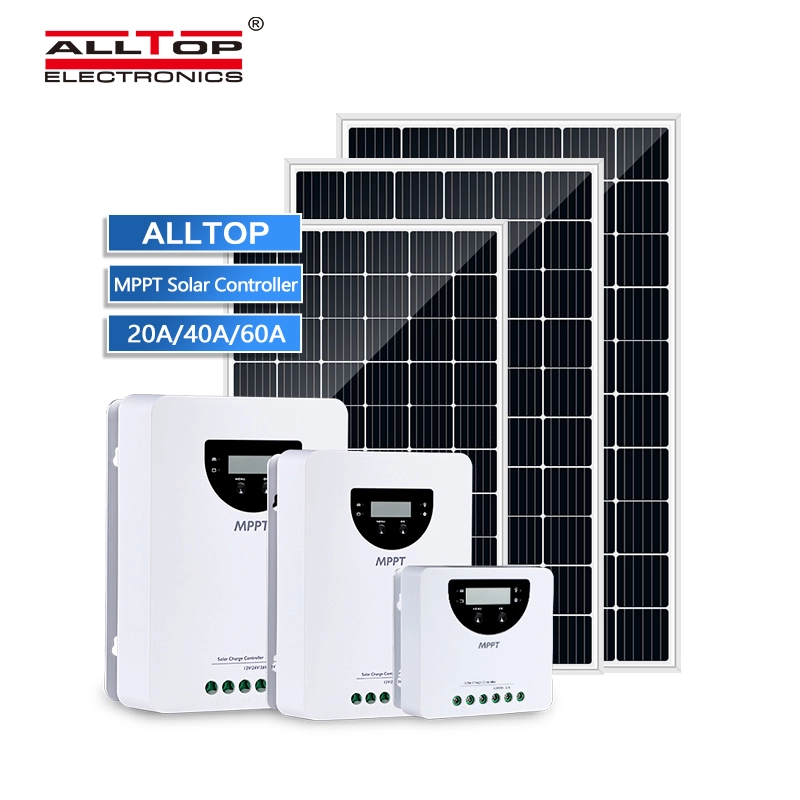
Lithium Battery 2022 Trending Products 12v Wifi Street Light 384v Charge Mppt Lamp Control Circuit Board 1.2v Solar Controller
| Model | STB1220 | STB1240 | STB1260 |
| Maximum Charging Current | 20A | 40A | 60A |
| System Voltage | 12/24V automatic identification | ||
| MPPT Charging Voltage | <14.5/29V | ||
| Maximum Battery Voltage | 35V | ||
| Overcharge protection voltage | 10.0~32.0V(lithium battery, default 14.4V) | ||
| Battery Type | gel, AGM, lead-acid, lithium (default gel battery) | ||
| Maximum PV Voltage | 100V(-20℃), 90V(25℃) | ||
| Maximum input power | 260W/520W | 520W/1040W | 750W/1500W |
| MPPT Tracking Range | battery voltage+1.0V)~Voc*0.9 *² | ||
| Output Current | 20A | 30A | 30A |
| Operating Mode | universal controller (default), street light mode, user manual mode | ||
| Maximum MPPT Tracking Efficiency | >99.9% | ||
| Maximum Charging Conversion Efficiency | 98.0% | ||
| Dimensions | 136.6*136.6*67.1mm | 196.5*136.6*97.1mm | 262.5*186.5*97.5mm |
| Weight | 830g | 1300g | 2500g |
| Self Power Consumption | ≤12mA | ||
| Communication | RS485(RJ11 port) | ||
| Operating Ambient Temperature | -20~+55℃ | ||
| Storage Temperature | -25~+55℃ | ||
| IP Rating | IP32 | ||
product description
1. Various tracking algorithms are combined to accurately track the maximum power point in a very short time
2. Innovative maximum power point tracking technology (MPPT), maximum power point tracking efficiency>99.9%
3. Full digital control technology, charging conversion efficiency up to 98% 4. The LCD screen dynamically displays the operating data and working status of the equipment
5.12/24/36/48V system voltage automatic identification
6. With real-time power statistics recording function 7. External temperature sensor, more accurate temperature compensation, improve battery life
8. Built-in over-temperature protection mechanism, when the temperature exceeds the set value, the charging current is derated, thereby reducing the temperature rise of the controller and avoiding high temperature damage to the controller
9. Double automatic limit function of rated charging current and charging power 10. Supports liquid, gel, AGM and Li-ion batteries 11. Four-stage charging of lead-acid batteries: MPPT, strong charge, balanced charge, and float charge
12. Internet of Things wireless communication, Bluetooth
communication or RS-485communication function optional
13. Bluetooth communication supports mobile APP to realize wireless
monitoringfunction of solar controller
14. Use high-performance, ultra-low-power Bluetooth dedicated chips.
15. Using Bluetooth 4.2 and BLE technology, the communication
distance can beup to 10 meters
16. The wireless communication of the Internet of Things realizes the
remote connection of the controller through loT/GPRS, without the need for
networking, which is convenient and fast
17. The wireless communication of the Internet of Things can remotely
monitor and control the system through the WeChat applet and PC terminal.
18. The wireless communication of the Internet of Things can
count and display the charge and discharge power by project group and month.
19. Use the standard Modbus communication protocol based on the
RS-485communication bus to maximize the communication needs of
different occasions
20. Excellent EMC design
21. Comprehensive electronic protection
In most cases, MPPT technology will "boost" the charging current of the solar
power system. For example, a system might have 8 amps flowing from the
solar array to the controller and 10 amps flowing from the controller to the battery.
The controller does not generate current, and the energy input to the controller is
equal to its output energy. Since power is the product of voltage and current
(volts x amps), the following holds true:
(1) Controller input energy = controller output energy
(2) Input voltage x input current = output voltage x output current * Assumes 100%
efficiency, ignoring power losses in wires and conversion. If the maximum power
point voltage (Vmp) of the solar array is greater than the battery voltage, the
battery charging current must be proportionally greater than the solar array output
current so that the input and output power can be balanced. The greater the difference between the Vmp voltage and the battery voltage, the greater the current boost.
Current enhancement is extremely important in the system because the maximum
power point voltage (Vmp) voltage of the solar panels in a solar power system is
usually higher than the battery voltage.
Traditional controllers connect the solar array directly to the battery during
charging. This requires the solar array to operate in a voltage range that is
typically lower than the maximum power point voltage. Taking a 12V system
as an example, the battery voltage range is usually 11-15 V, but the
maximum power point voltage of a solar array is usually around 16 or 17V.
The solar PV array maximum power point voltage Vmp is the voltage at
which the output power (amps x volts) is at its maximum. Since traditional
controllers do not always operate at the maximum power point voltage of
the solar PV array, energy is wasted that could otherwise be used to charge
batteries and power system loads. The greater the difference between the
battery voltage and the maximum power point voltage of the solar PV
array, the more energy is wasted. This series of controllers will always
operate at the maximum power point, reducing energy waste compared to
traditional controllers. The figure below shows the nominal 12V solar
cell I-V curve and output power graph.